I, Fiber optic cable
A, fiber composition and classification
1, fibre according to their manufacturing materials can be divided into different silica fibers and plastic optical fiber, quartz fiber commonly used fiber, silica fibers by their different transmission modes are divided into single-mode and multi-mode fiber. Plastic optical fiber composed entirely of plastic, usually for multiple modes for short distance applications.
2, the classification of silica fiber
Single-mode fiber
G.652A (B1.1 B1); G.652B (B1.1 B1); G.652C(B1.3); G.652D(B1.3) ; G.655A optical fiber (B4) (trunk); G.655B optical fiber (B4) (trunk)
Multimode optical fiber
50/125 (A1a A1); 62.5/125(A1b)
II, the structure of the cable
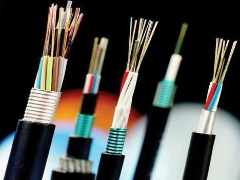
Outdoor optical fiber 1, main central tube type cable, stranded type fiber optic cable and slotted core cables three structures, by using optical fiber and optical fiber Ribbon can be divided into ordinary optical fiber cable with fiber ribbon cables 6 type. The structural characteristics of each cable:
(1) the Central tube type cable (standard: YD/T769-2003): the cable Center for loose tube, strengthen components around the loose tube fiber optic cable types, such as common GYXTW cable and GYXTW53 cable, cable core is small, usually 12-core following.
(2) the layer stranded type fiber optic cable (standard: YD/T901-2001): enhancing component is located in the center of the fiber optic cable, 5~12 loose tube stranding stranded on core strengthening, twisting usually SZ stranding. Such cables such as the GYTS, through the combination of loose tubes can get large core fiber optic cable. Stranded loose tube layer of color is usually red, green-collar as shown in chromatographic separations, loose tubes and used to differentiate different types of fibers. Layer stranded type fiber optic cable cores can be larger, at present the company stranded type fiber optic cable cores up to 216 cores or higher.
(3) the slotted core cable: strengthening component is located in the center of cable, made of plastic in the stiffening frame slot, fibre or fibre belt is located in the frame slot, fibre or fibre with less vulnerable to pressure, the flat crush resistance of fiber optic cable with good performance. This kind of structure cable at home is rare, the proportion of small.
(4) the 8-shaped self-supporting structures, the kinds of fibers can be incorporated into the Central tube layer stranded type fiber optic cable, largely because it singled out the cable structure and others are quite different. Usually have a central tube layer stranded Figure 8 self-supporting optical fiber cable.
(5) the coal flame retardant optical fiber cables (standard: Q/M01-2004 Enterprise standard): compared with the General cable, improved cable fire retardant performance requirements, and specially designed to make fiber optic cable suitable for using in mine environments, usually exterior sheathing color blue, in order to facilitate identification of cable in mine. According to the structure can be divided into the Central tube type cable with stranded type fiber optic cable in a two-class structure.
2, indoor optical fiber cable
Indoor fiber optic cables according to the classification of optical fiber core number, mainly single-core and dual-core and multicore cables, and so on. Indoor fiber optic cables is mainly composed of sleeve fiber, composed of woven nylon and PVC outer sheath. According to singlemode and multimode fibre types can be divided into two major categories, single mode indoor outer sheath of cables usually yellow in color, multimode indoor outer sheath of cables usually orange in color, there are some indoor cable outer sheath colour grey.
Three cables types of nomenclature
GY--outdoor optical fiber cables for telecommunication; GJ--indoor fiber optic cables; MG--Colliery cables
Strengthen the artifact types
(No model)--metal stiffening; F--non-metallic stiffening Member
Structural characteristics
D--optical band structure; (Unsigned)-loose tube-layer stranded type structure; X--Central tube type architecture; G--frame structures; T--padding; Z--flame retardant structure; C8--8-shaped self-supporting structure
Sheath
Y--PE sheath; W--with steel-polyethylene caking protective layers; S--steel and polyethylene caking protective layers; A--aluminum-polyethylene caking protective layers; V--PVC sheathed
Outer sheath
53-serving PE sheathed corrugated steel tape longitudinal; 23-wound steel tape armored PE sheathed; 33-thin wire wrapped serving PE sheath; 43-thick wire wrapped serving PE sheath; 333-double polythene jacket thin steel wire around and serving sets
Second, fiber-optic project
Design of optical fiber network system
Design of the fiber-optic system, follow these steps:
1. first find out what kind of network is to be designed by, their status, why use fibers.
2. According to the actual situation is a fiber-optic network equipment, selecting the appropriate cable, jumper and connect with other items. Selection should be based on available, and based on performance, price, services, and brands to be sure.
3. According to customer's requirements and network types determine the routing lines and draw a wiring diagram.
4. route accounting system is required for longer attenuation cushion accounts can be carried out according to the following formula:
Attenuation cushion = transmitting optical power-receiving sensitivity attenuation attenuation-of-line connection
(DB) where line = cable length x units decay; attenuation and fiber quality has much to do, generally single-mode 0.4~0.5dB/km; multimode for 2~4dB/km.
Coupling attenuation, including splice joints decay weld decay associated with welding tools and personnel's quality, hot-melt for 0.01~0.3dB/Cold Fusion 0.1~0.3dB/; connector attenuation quality has much to do with the joints, usually 1dB/. General least 4dB attenuation cushion systems.
5. When accounts are not qualified, shall be revised as appropriate design and accounting. This situation may sometimes be repeated several times.
1. design examples:
1. the transformation of the campus network 1: according to its circumstances, is already a thin line one side of the net with a LANart three repeaters (twisted-pair cable-fiber optic-thin line), on the other side using a LANart's twisted with fibre backbone HUB. For overhead or underground tube type of outdoor 4 core multimode fiber optic cable through weld ST head indoor jumper (due to optical fiber interface device for the ST). Accounting for attenuation: (General multimode devices in the 2km range have accounted here only as an example)
Transmit power: -16dBm
Receiver sensitivity: -29.5dBm
Line attenuation: 1.5kmx3.5dB/km=5.25dB
Connection attenuation: connector 2 attenuation: 2 point x1dB/point =2dB
Weld two points as follows: attenuation margin = 2 point x0.07dB/point =0.14dB -16 dBm-( -29.5dBm) -5.25 dB-0.14dB-2 dB =6.11 (dB) by means of the above calculation, we can see that system larger than 4dB, can meet the requirements of the above options.
2. renovation of campus network 2: it is 14 buildings with fibre optic connection, each building has its own subnet (10Mbps Ethernet), the adjacent spacing between each building are less than 2km. Consider using a double loop do FDDI trunk, put one in each building FR2100 FDDI/Ethernet bridge double ring, outdoor pipes with 6-core cable to connect them.
Splice method is used within each building, 6-core outdoor optical cable adapter with three FDDI standard MIC jumper to connect FDDI bridge. Each building to weld within 6 points, but requires an input and eight output fiber terminal box, 14 buildings on a total of 21 MIC jumper 14 terminal box 84-melting point, 14 paragraph 6 outdoor optical fiber core double loop networks and 14 FDDI/Ethernet bridge. Because the floor space is small (less than 2km), and therefore generally not accounting for attenuation cushion.
PREV: 没有了